Future Homes Standard 2025:
A Complete Guide To Building Regulations & ICF Performance
The Future Homes Standard 2025 represents a transformative shift in how new homes will be built in England. Set to come into force around 2025-2027, the Future Homes Standard (FHS) updates Part L of the Building Regulations to establish minimum performance standards for new dwellings. This includes requirements for fabric efficiency, low-carbon heating systems, and overall emissions targets.
The goal is clear: new homes must be “zero-carbon ready” and produce approximately 75-80% lower carbon emissions compared to homes built under 2013 UK Buildings Regulations, with no fossil-fuel boilers and typically featuring solar PV panels alongside high airtightness and insulation levels.
Understanding The Home Energy Model
The Home Energy Model serves as the new government calculation methodology designed to replace SAP for assessing dwelling energy performance and calculating Energy Performance Certificates (EPCs). Being rolled out in phases alongside SAP 10.3 as an interim route, this model employs a more dynamic approach using half-hourly timesteps and detailed treatment of fabric and systems.
This advanced methodology models energy use and emissions by comparing results against a notional FHS dwelling, providing a more accurate representation of real-world performance.
Affects of the Future Homes Standard on House Design
|
Aspect |
Future Homes Standard |
Home Energy Model |
|---|---|---|
|
Type |
Regulation / policy standard for new homes. |
Technical calculation methodology and software framework. |
|
Purpose |
Will define required energy, carbon and heating performance for new dwellings (e.g. zero‑carbon‑ready, no gas boilers). |
Quantify energy use, emissions, etc., to check if a dwelling meets FHS and other policy tests. |
|
Legal Status |
Forms part of Building Regulations; mandatory once in force. |
Approved methodology referenced by regulations; used to evidence compliance. |
|
Relation to SAP |
Successor framework to current Part L standards based on SAP 10.2/10.3 outcomes. |
Direct replacement for SAP as the official energy model for dwellings, introduced alongside FHS. |
|
Schedule |
Due to be adopted in England around 2025–2027 with transitional arrangements. |
First “live” FHS‑assessment version goes live with or shortly after FHS; dual‑method period with SAP 10.3. |
Under the Home Energy Model, ICF gets a more favourable and realistic treatment on thermal mass and dynamic performance, while U‑value targets are essentially set by the Future Homes Standard 2025 notional, not by HEM itself.
Thermal Mass Treatment
HEM explicitly models the entire thickness of opaque elements for thermal mass, distributing areal heat capacity across multiple internal nodes; this contrasts with SAP’s monthly method which only uses the kappa value for the limited “active” thickness at the internal surface and this is capped at a depth of 100 mm.
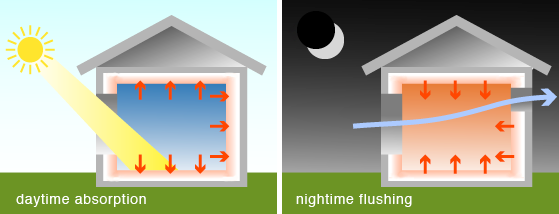
For an ICF wall, the full concrete core now contributes to the thermal mass in the simulation, so the slow response and buffering seen in empirical ICF studies (reduced heat loss and moderated internal temperature swings) will be captured rather than ignored
Implications for ICF behaviour
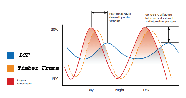
Dynamic studies on ICF show around 30–40% lower transient heat loss and cooler internal temperatures compared with lightweight walls at the same steady‑state U‑value, due to the mass working through the insulation; HEM’s time‑step and whole‑wall mass approach is designed to resolve exactly these transient effects.
In practice this will mean ICF is less penalised by simplistic daily or monthly averaging and should show reduced peak loads and more stable zone temperatures under HEM, particularly helpful for heat pump sizing and overheating checks.
U values
The Future Homes Standard consultation will keep the notional external wall U‑values at 0.18 W/m²K, floors at 0.13 W/m²K and roofs at 0.11 W/m²K, and these values will form the FHS notional dwelling target irrespective of construction type.
HEM will allow the same U‑value ICF wall to demonstrate better overall performance in the dynamic energy and comfort outputs than a lightweight wall with the same U‑value.
The True Benefits of ICF will be revealed
Realistic Calculations
ICF’s low U-Values + High Thermal Mass aligns with ‘fabric first’ objective set out by HEM & FHS. ICF is moving from being under-credited in SAP to being modelled closer to real world performance.
No Longer Ignored
The Home Energy Model will unlock the concrete core benefits that SAP mostly ignores. Meaning that for the same U‑value you will see lower dynamic heat loss and smoother temperatures in the HEM.
How Will this work in Practice?
Let’s compare ICF Walls to Timber Frame:
Conceptual Walls
ICF wall say 150 mm concrete core between two EPS leaves, plus internal lining with U ≈ 0.18 W/m²K to match FHS notional.
Timber frame wall say 140 mm stud with mineral wool, sheathing and insulated sheathing, internal plasterboard with U ≈ 0.18 W/m²K also.
SAP Interpretation
SAP collapses thermal mass into a single Thermal Mass Parameter using kappa values based only on the first 100 mm of material in contact with internal air so that the ICF’s concrete core behind the EPS is largely absent from that calculation.
The dynamic buffering of the ICF core is therefore not properly credited because SAP sees them as broadly similar on heating demand, with only minor differences from internal linings and partitions.
HEM Interpretation
HEM assigns an areal heat capacity to each wall based on the entire thickness of the element and distributes it through five internal nodes in a dynamic heat‑balance model with 30 minute time steps.
For the ICF wall this means the full volume of concrete participates in storing and releasing heat, so the model now “sees” the mass acting through the insulation, rather than treating the wall as almost purely lightweight insulation with a thin internal lining.
ICF homes deliver substantial energy savings and superior comfort that SAP ignores. The Home Energy Model will correct this, officially crediting ICF construction for its year-round performance benefits.
Dynamic Performance Results:
| Aspect | ICF wall (U ≈ 0.18) | Timber frame wall (U ≈ 0.18) |
| Steady‑state heat loss | Similar, because U‑values are matched. | Similar, by definition. |
| Transient heat loss | Empirical work on ICF shows ≈ 37 % lower transmission losses over cold spells versus a lightweight wall at the same U, due to stored energy in the concrete. | Much closer to steady‑state; little reduction in effective U under fluctuating conditions. |
| Indoor temperature swings | ICF homes run about 2 °C cooler in free‑float warm periods at equal U‑value, reflecting the buffer effect of the core. | More rapid indoor temperature swings, following external conditions more closely. Timber frame buildings will need Mechanical Ventilation systems that will adversely affect their EPC ratings. |
| HEM representation | Whole‑wall mass and time‑step simulation capture the reduced peaks and delayed responses, so heating/cooling loads and overheating risk reflect that buffering. | Lower areal heat capacity input and faster response, so demand profiles remain similar to traditional SAP results. |
The Future of Sustainable Construction
SAP does not identify the dramatic reduction in energy costs and additional comfort levels in the different seasons provided by an ICF House. However, the Home Energy Model will. This represents a significant advantage for ICF construction under the Future Homes Standard 2025, as the methodology finally recognizes and credits the true thermal performance of high-mass construction systems. With the Future Homes Standard implementation approaching, ICF offers builders and developers a proven pathway to meet stringent performance requirements while delivering superior comfort and energy efficiency for homeowners.
Ready To Control Your Project Costs?
Discover the ICF Advantage and see how high-mass construction offers unmatched thermal performance and year-round comfort. Contact the ICF Design team today to discuss your project.